LDR INTERFACING WITH ARDUINO
A light-dependent resistor, or photoresistor, is a sensor whose resistance decreases as the amount of light falling on it increases. In this tutorial you will learn how to interface a LDR with Arduino (by using ATmega 328p).
Synopsis

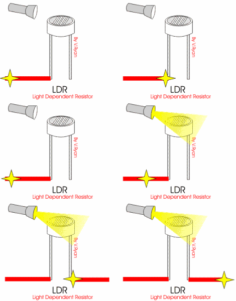
A light-dependent resistor, or photoresistor, is a sensor whose resistance decreases as the amount of light falling on it increases. When it is dark, the resistance of a photoresistor may be as high as a few MΩ. When it is light, however, the resistance of a photoresistor may be as low as a few hundred ohms.

In this tutorial you will learn how to interface a LDR with Arduino (by using ATmega 328p).

Description

An LDR is a component that has a (variable) resistance that changes with the light intensity that falls upon it. This allows them to be used in light sensing circuits.

This resistor works on the principle of photo conductivity. It is nothing but, when the light falls on its surface, then the material conductivity reduces and also the electrons in the valence band of the device are excited to the conduction band. These photons in the incident light must have energy greater than the band gap of the semiconductor material.This makes the electrons to jump from the valence band to conduction.

Types of light Dependent Resistors

Light dependent resistors are classified based on the materials used.

1. Intrinsic Photo Resistors

These resistors are pure semiconductor devices like silicon or germanium. When the light falls on the LDR, then the electrons get excited from the valence band to the conduction band and number of charge carriers increases.

2. Extrinsic Photo Resistors

These devices are doped with impurities and these impurities creates a new energy bands above the valence band. These bands are filled with electrons. Hence this decrease the band gap and small amount of energy is required in moving them. These resistors are mainly used for long wavelengths.

This is a simple project that focuses on eliminating darkness. Whenever a room gets dark due to a fused bulb or any other factors, a light bulb automatically turns ON. This can even be used as an emergency lighting system. It can be used to automatically turn a light ON whenever there isn’t sufficient light in a room.

In order to detect the intensity of light or darkness, we use a sensor called an LDR (Light Dependent Resistor). The LDR is a special type of resistor which allows higher voltages to pass through it (low resistance) whenever there is a high intensity of light, and passes a low voltage (high resistance) whenever it is dark. We can take advantage of this LDR property and use it in our DIY Arduino LDR sensor project.

In this experiment, we will connect a photoresistor to an Arduino analog input and read the value with the analogRead() function. Depending on the value the Arduino reads, the program will then set pin 9 HIGH or LOW to turn on or turn off the LED night lights. The threshold value is 150. When the analog value read is less than 150, the Arduino will turn the LEDs on. When the analog value it reads is below 150, the Arduino will turn the LEDs off.

If the room is lighted, the LEDs should not light. Try getting them to turn on it by covering the photoresistor with your hand. Remove your hand and observe that they turn off again.

Applications of Light Dependent Resistor

>> The price of the LDR is very less and it is very simple in structure.

>> In the light sensor the resistors are used frequently.

>> These resistors are used to sense the presence & absence of light like alarm circuits, alarm clock, light intensity meters and etc.

Proteus design for LDR interfacing with Arduino


Orcad design for LDR interfacing with Arduino


LDR interfacing with Arduino

/*  Name     : main.c
 *  Purpose  : Source code for LDR Interfacing with Arduino.
 *  Author   : Gemicates
 *  Date     : 29-01-2018
 *  Website  : www.gemicates.org
 *  Revision : None
 */

#include"Arduino.h" 
const int led=9;                                 // variable which stores pin number

void setup() 
{
  pinMode(led, OUTPUT);                          //configures pin 9 as OUTPUT
}

void loop() 
{
   int sensor_value = analogRead(A1);
 
    if (sensor_value > 150)                      // the point at which the state of LEDs change 
    { 
      digitalWrite(led, HIGH);                   //sets LEDs ON
    }
   
   else
    {
      digitalWrite(led,LOW);                     //Sets LEDs OFF
    }

}
Error message here!

Show Error message here!


Forgot your password?

Error message here!

Send OTP

Error message here!

Show Error message here!


Lost your password? Please enter your email address. You will receive a password you Need.

Send Error message here!


Back to log-in

Close